
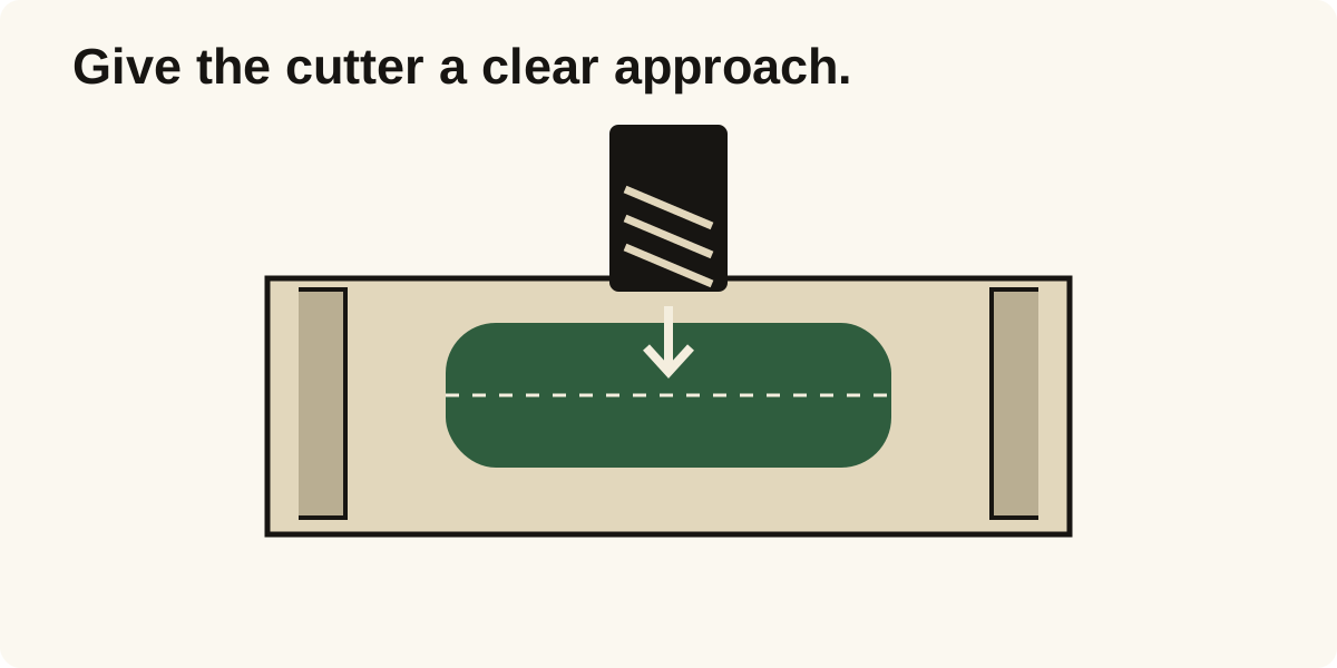
Design for machining means shaping a part so cutting tools can reach its features, workholding can support it, and inspection can verify what matters.
A model can be valid CAD and still create a difficult machining job. A square internal corner, a tall flexible wall, or a hole hidden behind a flange changes the tools and setups needed to produce it. Review those decisions while changing the model is still easy.
At twentyfour26, the prototype machining review starts with a STEP file and checks the actual geometry against a defined cell. 6061-T6 aluminum is stocked. That makes the useful first question concrete: can this part be reached, held, cut, and checked with the requirements you have given it?
1. Check tool access from the outside in
Imagine the cutting tool approaching each face of the part. A hole, pocket, or side slot needs a path for the cutting edge, enough reach to finish the feature, and clearance for the larger tool holder above it. Seeing the floor of a pocket in CAD is only the first check. A tall neighboring wall can block the holder before the cutter reaches that floor.
Group features that can be cut from the same direction where the assembly permits it. A plate with holes on one broad face may be straightforward to hold. Add holes on several edges and the shop may need to reposition it. Each setup must locate the part again and preserve the relationship between features cut at different times.
For a hidden mounting hole, consider moving the fastener to an accessible face, opening a clearance path, or separating the component into pieces. Choose the change that preserves the joint and assembly access. A split part brings its own fasteners and alignment requirements, so it should solve more trouble than it creates.
2. Give internal corners a workable radius
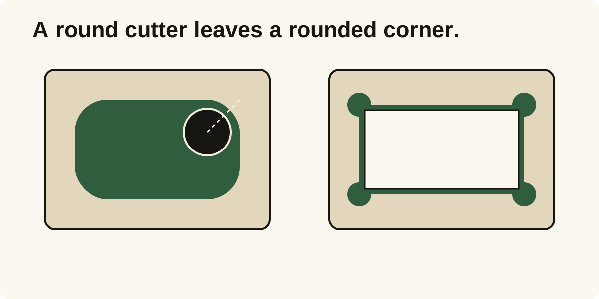
A rotating end mill leaves a radius in a pocket's vertical internal corners. A perfectly square corner in the model cannot be made by simply driving a round cutter farther into it. Start by checking the mating component: does the corner actually need to be sharp, or does the part only need enough clearance for an insert, board, or bracket?
When function permits, enlarge the internal radius and leave space for a cutter smaller than the corner's limiting geometry. Sandvik Coromant's corner-milling guidance explains that cutter engagement increases inside a corner, raising load and vibration risk. Extra room gives the machining plan more freedom to manage that engagement.
A square insert can sometimes clear a rounded pocket by adding local corner relief, often called a dog-bone relief. Check that the relief leaves enough material around fasteners and sealing faces. If the sharp corner itself performs a job, identify that requirement instead of silently rounding it away. The process may need to change.
3. Review deep pockets with the cutter in mind
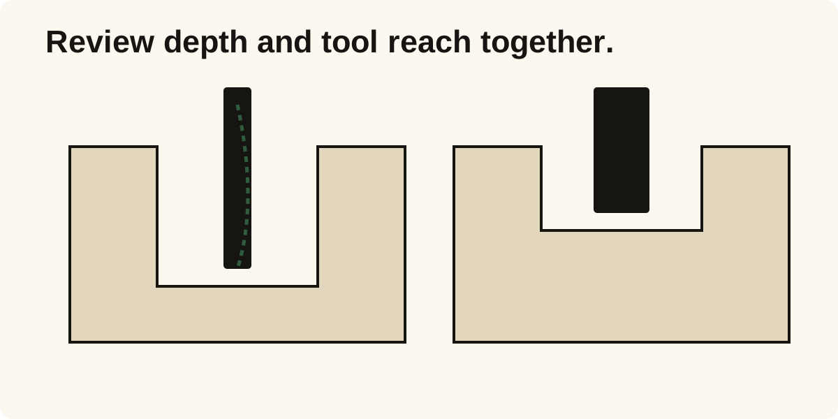
A deep narrow pocket combines a long reach with limited room for a stiff tool. The extended cutter can deflect, chips are harder to clear, and the holder still needs clearance at the top. A small radius at the bottom of a tall pocket makes the problem harder because it can force a narrow tool to do the deepest work.
Decide what sets the depth. If the pocket clears an electrical component, use the real component envelope and assembly allowance. If it removes weight, check whether a shallower, wider pocket or an open profile can achieve the same purpose. Do not remove extra material just because the unused space looks available in CAD.
There is no single depth-to-width ratio that accepts every pocket. Material, cutter diameter, exposed length, finish, and support all affect the plan. Flag the deepest and narrowest region, then change depth or radius where the function gives you room. Leave the cutting strategy to the shop.
4. Keep walls stable and leave somewhere to clamp
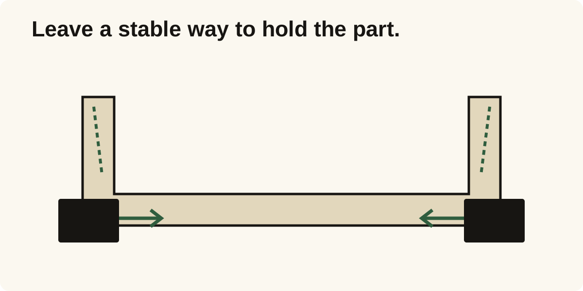
A wall can move under cutting force or clamping pressure, then spring back after machining. Height matters as well as thickness. A short rib supported at both ends behaves differently from a tall freestanding fin, even when their modeled thickness is identical.
Look for uninterrupted rigid surfaces where the part can sit and where a vise or fixture can hold it. An enclosure with delicate walls on every edge may lose its obvious gripping surfaces as material is removed. A sturdy base, accessible pads, or a different machining order can help, but the final design needs to leave room for that plan.
Sandvik Coromant's thin-wall milling guidance ties the machining method to wall height, thickness, and the stability of the tool and component. Treat a minimum wall figure as a discussion about this geometry and material, rather than a number to copy into every design.
5. Make holes and threads unambiguous
Use standard fasteners and familiar hole sizes when they meet the assembly requirement. Separate a clearance hole from a locating bore: the first lets a fastener pass, while the second may position a mating feature. They need different attention even if their diameters look similar.
A blind drilled hole normally has a pointed bottom. Specify a flat bottom only when the part needs one, because that changes the work required. Check the remaining material beneath the hole and make sure a drill can start on a suitable entry surface without meeting an edge or steep slope.
For threaded holes, distinguish usable thread depth from drilled depth. The thread designation should identify the finished thread, with its location and quantity. Use the thread-callout guide for the details. Modeling a decorative helix is less useful than making the required thread and engagement clear on the drawing.
6. Put precision and finish where the assembly needs them
Identify the interfaces that locate, seal, guide, or support another part. A bearing seat, a mounting pattern, and a cosmetic outer edge do different jobs. Protect the first two with appropriate dimensional and geometric requirements, then let noncritical geometry use a suitable general tolerance.
A hole can be the correct size and still sit in the wrong place. Connect critical locations to the faces or datums that establish the assembly. Plan how the result will be measured, especially when the feature is inside a narrow cavity or is hidden after another operation.
Finish requirements also need a location and a reason. Identify the sealing face, sliding contact, or visible surface that needs attention. For coated parts, establish which finished condition controls mating dimensions and threads. The CNC machining tolerances guide explains how to separate functional requirements from unnecessary precision.
7. Work through the next prototype revision
Consider a hypothetical electronics enclosure with a deep pocket, square internal corners, a thin outer wall, and a lid located by a screw pattern. Begin with the board and connector clearances. Those define the space that must stay, while unused pocket depth and corner shape may be available to change.
Give the pocket corners enough relief for the board's actual outline, then reduce depth where the components allow it. Keep material around the mounting bosses and inspect the wall beside each connector opening. A thinner wall may save weight but leave less support during cutting or less strength around a screw.
Finally, control the relationship between the lid, mounting pattern, and connector openings. Avoid tightening every outer dimension to solve a problem caused by the wrong locating surfaces. Export the revised model and update its drawing together. The useful outcome is a component that tests the enclosure's real interfaces with fewer avoidable manufacturing constraints.
8. Send a consistent model and drawing
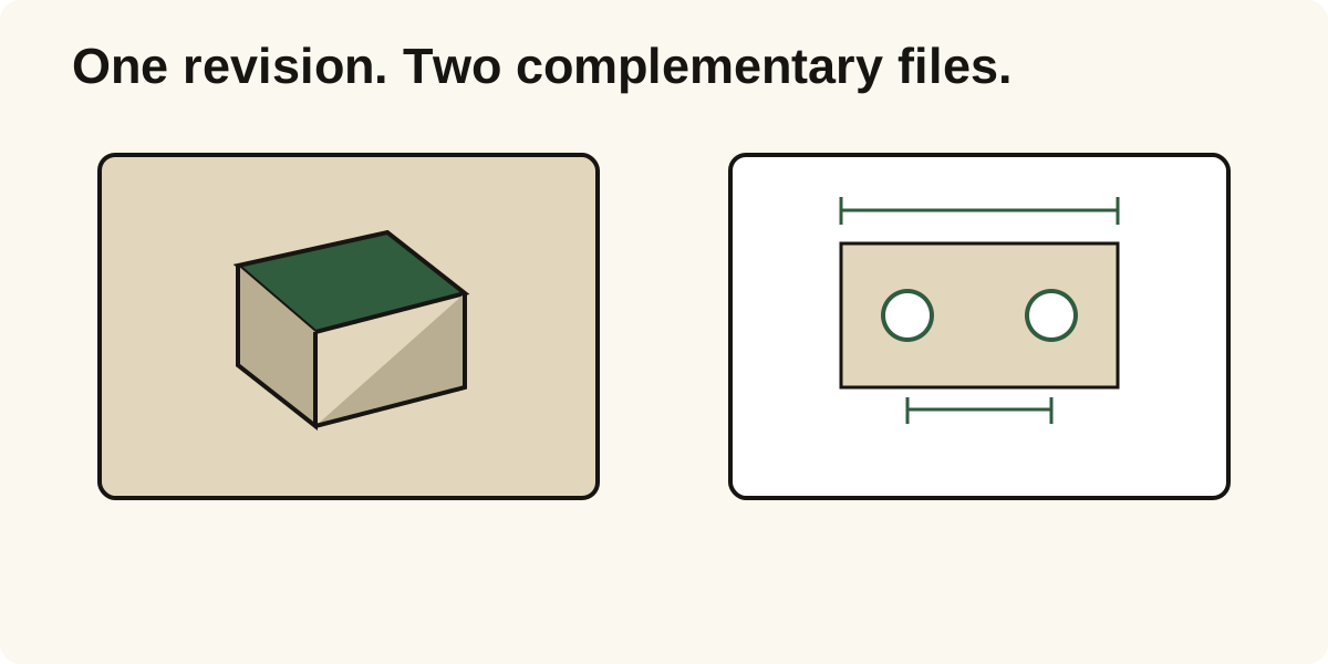
The STEP model describes the shape. A drawing adds the requirements a shop should not infer: tolerances, threads, surface finish, material condition, and inspection needs. Give the drawing a revision identifier that matches the model, so the shop can tell which files belong together.
Before sending the part, complete this release checklist:
- Reopen the exported STEP file and check the intended body and overall size.
- Match the model and drawing revision; remove superseded versions from the handoff.
- State the material, grade or condition, required quantity, and intended finish.
- Check cutter access, internal radii, deepest pockets, and tall unsupported walls.
- Identify the faces that locate the part and the surfaces available for holding it.
- Specify threads, usable engagement, and critical fit or location requirements.
- Mark any inspection evidence needed and explain what the prototype must test.
Bring the actual geometry to twentyfour26
Send the STEP file and attach the drawing when tolerance or finish requirements matter. twentyfour26 checks whether the part fits its machining cell, flags features needing attention, and turns accepted designs into a quote and machining plan. Include the purpose of a critical interface so the review can focus on what the prototype must prove.
Frequently asked questions
What is the difference between DFM and DFA?
Design for manufacturing (DFM) concerns how individual components are produced. Design for assembly (DFA) concerns how those components go together, including fastener access, orientation, and the number of separate pieces. A two-piece housing might be easier to machine but harder to assemble, so evaluate both jobs before splitting a part.
Can CNC machining make undercuts?
Some undercuts can be reached with tools such as T-slot or lollipop cutters, provided the tool can enter and clear the surrounding geometry. A hidden feature with no entry path needs a different design or process. Include the required undercut shape in the model and check access before assuming it suits a particular shop.
Should a machining drawing use inches or millimeters?
Either can communicate the part clearly. State the drawing units explicitly, keep the dimensioning consistent, and check a known overall dimension after exporting and reopening the model. A scaling mismatch can change stock size, tool access, and the whole machining plan.
How should I specify a machined logo or text?
State whether the marking is cosmetic, identification, or a functional feature. Give its location, size, and required depth if depth matters. Fine raised lettering creates delicate features, while narrow engraved strokes constrain tool size. A clear marking note lets the review separate essential identification from optional detail.
Related posts
CNC Machining Tolerances: A Practical Guide
How to specify the few dimensions that control fit and function without turning every feature into an expensive constraint.
Read articleThread Callouts: What to Put on a CNC Drawing
A practical guide to specifying threaded holes clearly, from size and class to usable depth and the details a shop should not have to guess.
Read article